︎︎︎︎︎︎
mood:
Vitamins!
NODES
Feb 18, 2022
Language: English
This is the documentation of my current progress on making smart cookware.
Motivation
I wanted to make rice wine (酒酿,jiǔ niàng) for the lantern festival on Feb 15. I used an instapot for the first try. It has a yogurt function that keeps the water at 43°C and the container at 35°C. I thought it would be a good starting point but it turned out that more acid and alcohol was produced if the temperature goes above 30°C. To have a more precise control over the temperature, I decided to buid my own.
Matthew Arbesfeld wrote this very useful documentation and I refer to it for parts. They used custom PCB but it can be easily transferred to an Arduino, which is what I used for rapid prototyping.
Parts
This is (probably) all you need:
- a microcontroller, I'm using Arduino Uno, using other microcontroller may require different pinout.
-
some jumper wires, alligator clips, what have you
-
a solid state relay. This one is a overkill as the current of my components is way below its limit, but it is a safe choice.
-
some number of immersion water heaters. The number will depend on the size of the container (hence the amount of water that needs to be heated up), the target temperature and room temperature (hence temperature difference), and wattage of the heater.
-
DS18B20 waterproof one-wire thermometer
-
some kind of stirring equipment. I use a propeller with a DC motor. There are other choices like submersive water pump.
-
something to power the microcontroller. I used a 3.5 mm barrel jack power adapter. Noted that the DC motor, LCD screen, and LEDs are all powered by the same source, it's going to drink up some current. 1A is the bare minimum. I may alter the circuit to include another power supply to all these components later. It is always smart to use separate power sources for logic and for components - says the smart Nadya.
-
a crimper.
Circuit design
These are the features I want in my circuit.
-
precise temperature control, enabled by the thermometer and the water heater.
-
a display that tells me the current temperature reading. It's not super necessary but a nice feature to have. The serial monitor in Arduino IDE could do the same but it required the computer to be connected.
- two LEDs that tells me whether the heater is ON or OFF. This is also not necessary as the LCD screen could already do that, but I like the implication of a status LED and how people use solid-on, blinking, breathing etc. on a single LED to design status indicator.
-
water circulation. You can feel with your hand that the water near the water heater is much warmer than the water farther away in the same container. It's going to impact the precision and render the purpose of having a feedback loop pointless.
One component at a time
My best advice for designing such circuit is that one should tackle one component at a time.
SSR
The solid state relay is kind of new to me, especially when I live in the fear of being electrocuted by the mains electric power.
I cut open the hot wire and connected the end that's going to the wall socket to #1 on the SSR and the other end that's going to the water heater to #2 on the SSR. #3 is connected to a digital output pin on the Arduino and #4 is sharing the common ground with Arduino.
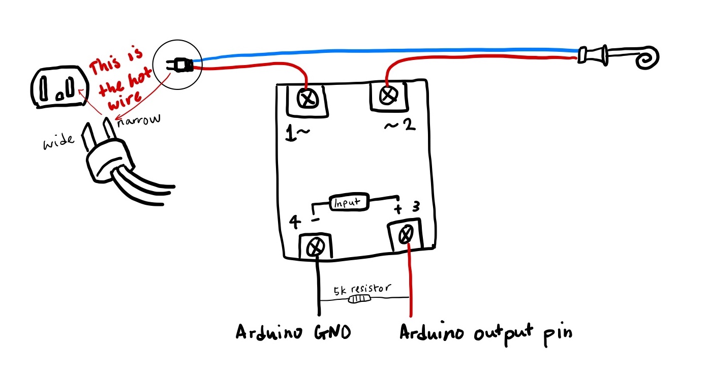
I simply used serial monitor to test if the circuit is working by putting the water heater into a cup of water. DO NOT TOUCH THE STEEL PART ON THE WATER HEATER WITH YOUR HAND when it's powered! And DO follow the instruction on using the water heater.
DS18B20
Connect the thermometer to complete the feedback loop. This digital temperature sensor has a one-wire interface, which means the signal is transmitted to the microcontroller digitally through one port pin. It is usually the yellow wire, but always refer to the datasheet.
The product that I bought comes in with a connector terminal, which is easier to work with a breadboard.
Stirrer
This low-budget mechanical stirrer uses a DC motor and a propeller and a pulley system to drive. I 3D printed a holder to fit the motor and the axle. This is a good reference for a way to arrange all components.
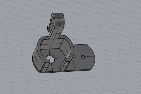
I used an IRLB8721 transistor to turn the motor on and off, this will be especially useful when I switch to a high-torque motor that requires a higher power supply. I also connected the motor to a PWM pin so that I can control its speed.
LCD display
The LCD I have came with a backpack. If it does not have a backpack, the wiring will be a bit more complicated; if it is not pre-soldered, follow this instruction.
In the same tutorial lady ada tells us how to connect the backpack to an Arduino.
> 5V to your 5V power pin - don't use 3.3V power, the LCD needs 5V for contrast! The I2C pullups are fairly weak so you can use use 3.3V logic for SDA/SCL even if the board is powered with 5V
> GND to Ground
> DAT (SDA) to I2C Data (on the Uno, this is A4, on the Mega it is 20 and on the Leonardo digital 2)
> CLK (SCL) to I2C Clock (on the Uno, this is A5, on the Mega it is 21 and on the Leonardo digital 3)
LEDs
This is the simplest part and could be skipped. However, make sure the current-limiting resistors have the correct resistance.
And the whole circuit diagram is here:
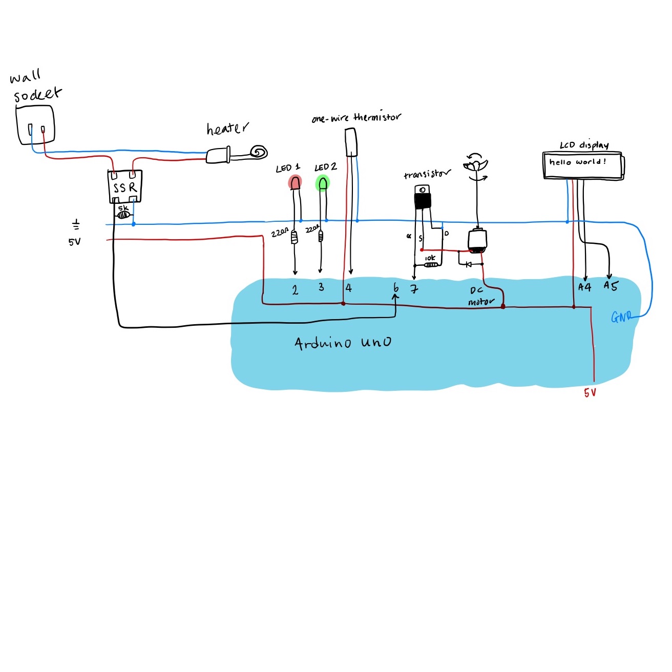
Everything is unpolished just yet.

I replaced all the jumper wires with less messy breadboard wires. These wires stick better to the breadboard, though I had to rearrange some components to minimize wire crossing. In this photo, the LEDs are moved from pin 2 and pin 3 to pin 12 and pin 13 to make room, the 5V and GND lines were not connected to the uno, and I forgot to wire pin 7 to the gate of the transistor. Use this as only a stylistic reference.

Code
Like my advice for testing each component, code should also be writen piece by piece. There is almost no exact reference online that will match what you want. Using other's code is sometimes helpful, but could bring more trouble than it could solve if you don't own it!
I'll start by the example code of each library. For example, if I'm testing the temp sensor, all I do is this:
#include <OneWire.h>
#include <DallasTemperature.h>

// Data wire is plugged into port x on the Arduino
#define ONE_WIRE_BUS x

// Setup a oneWire instance to communicate with any OneWire devices (not just Maxim/Dallas temperature ICs)
OneWire oneWire(ONE_WIRE_BUS);

// Pass our oneWire reference to Dallas Temperature.
DallasTemperature sensors(&oneWire);

void setup(void)
{
  // start serial port
  Serial.begin(9600);
  Serial.println("Dallas Temperature IC Control Library Demo");

  // Start up the library
  sensors.begin();
}

void loop(void)
{
  // call sensors.requestTemperatures() to issue a global temperature
  // request to all devices on the bus
  Serial.print("Requesting temperatures...");
  sensors.requestTemperatures(); // Send the command to get temperatures
  Serial.println("DONE");

  Serial.print("Temperature for the device 1 (index 0) is: ");
  Serial.println(sensors.getTempCByIndex(0));
}
Once I see it work, I'll simply change the loop to request the reading I need.
Here is a snippet of my code:
/*
hello! i'm danli, i wrote this firmware to operate my slow cooker!
any questions should be addressed to danlil at uw dot edu
 */
#include <OneWire.h>
#include <DallasTemperature.h>
// include the library code:
#include "Wire.h"
#include "Adafruit_LiquidCrystal.h"
// Connect via i2c, default address #0 (A0-A2 not jumpered)
Adafruit_LiquidCrystal lcd(0);
// Where the temperature sensor probe is connected.
#define ONE_WIRE_BUS 4 //need 4.7k pull-up to stablize data transfer

// Setup a OneWire instance to communicate with any devices.
OneWire oneWire(ONE_WIRE_BUS);

// Pass our oneWire reference to Dallas Temperature.
DallasTemperature sensors(&oneWire);

// define relay pin
int relayPin = 7;

// define motor pin
int motorPin = 6;

// let's add 2 leds to indicate heater status
int ledON = 2; //red one!
int ledOFF = 3; //maybe a green one?

void setup() {
  // put your setup code here, to run once:
  Serial.begin(9600);
  pinMode(relayPin, OUTPUT);
  pinMode(ledON, OUTPUT);
  pinMode(ledOFF, OUTPUT);
  pinMode(motorPin, OUTPUT);
  digitalWrite(relayPin, HIGH);
  sensors.begin(); //start up the thermometer library
    // set up the LCD's number of rows and columns:
  lcd.begin(16, 2);
  // uncomment this line to save some power
  lcd.setBacklight(LOW);
  // Print a message to the LCD.
  lcd.print("hello!");
}

void loop() {

  sensors.requestTemperatures();
  float tempC = sensors.getTempCByIndex(0);
  if (tempC < 29){ // lower bound for turning on the heater
    digitalWrite(relayPin, HIGH);
    analogWrite(motorPin, 63);
    // the motor draws a lot of current, so I pwm'ed it to have just enough amount of turbulance
    lcd.setCursor(0, 0);
    lcd.print("heater on!");
    digitalWrite(ledON, HIGH);
    digitalWrite(ledOFF, LOW);
    delay(100);
  }
  if (tempC >= 31){ // upper bound for turning off the heater
    lcd.setCursor(0, 0);
    digitalWrite(relayPin, LOW);
    digitalWrite(motorPin, LOW);
    lcd.setCursor(0, 0);
    lcd.print("heater off...");
    digitalWrite(ledON, LOW);
    digitalWrite(ledOFF, HIGH);
    delay(100);
  }
  lcd.setCursor(0, 1);
  lcd.print(tempC);
  delay(2000); //read temp only per 2 seconds
}
Noted that I set the upper bound and lower bound because I did not want to exaust the heater when it switch between on and off state at a set temperature. But it is totally capable of lingering.
Demosssss!
I got a big pot of water and taped everything I needed in water on the side of the pot. When I turn it on, the heater will start heating and the motor will start stirring.
When the temp goes beyond my set limit, everything is shut off until the temp drops below the lower bound.
Update Mar 14: the latest version has modularized every component in an arrangement.
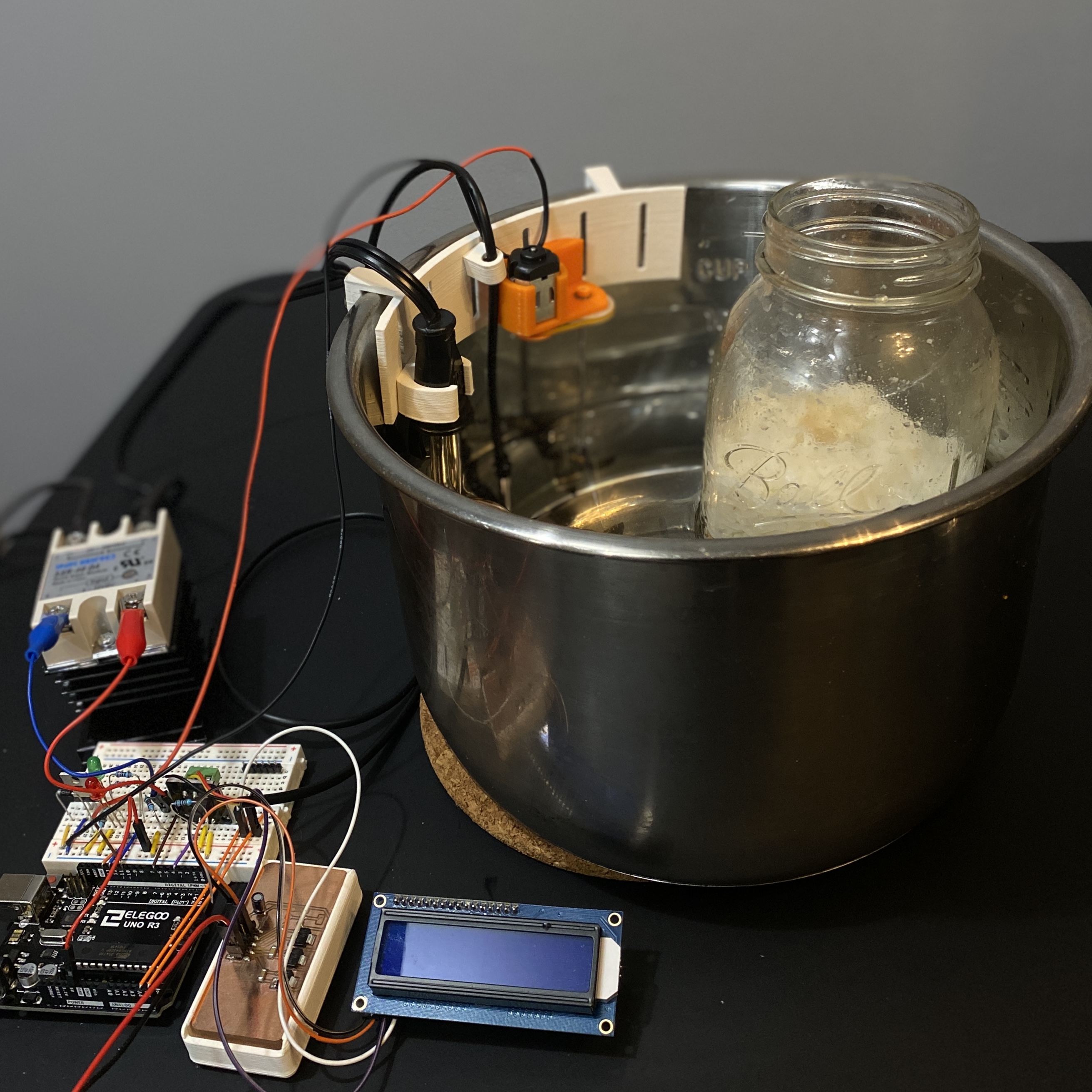
And the Jiuniang tastes good.